Ignition Coil Wiring Diagram / Wiring Diagram Ignition Coil Resistor Hobbiesxstyle. Discover (and save!) your own pins on pinterest The typical automotive ignition system prior to 1974 consisted of a coil and ballast resistor, with breaker points to interrupt the current flow when a spark was needed. Wiring diagram for ignition coil more information find this pin and more on 63 f100 wiring by ben platt. How to wire up the ignition on older cars with points and coil. Vw beetle coil wiring diagram kawasaki ignition how to replace an on alternator 87 ford relay electrical circuit maverick 74 19 gm 1996 silverado dz 5431 schematic 94 302 distributor 68 switch hot spark electronic kit 2003 1969 71 vintage diagrams simple fried wire 2001 cabrio 2010 camaro chrysler 407 ignitor 2 fiat uno user mallory 29440 full.
It shows the components of the circuit as simplified shapes, and the capacity and signal friends between the devices. The purpose of the ignition system is to create a spark that will ignite the fuel air mixture in the cylinder of an engine. The pip (profile ignition pickup) is the defacto crankshaft position sensor and is located inside the distributor (although in the wiring diagram it's not illustrated as so). Accuspark wiring diagrams diagram basic 12v full 1929 a 6v to help ignition system basics matt dubanoski 5 4 8 primary farmall international tractor for ford 9n 2n 8n converting 12 volt one wire alternator your boat systems short course 3 typical car starting t x you understand ferguson conversion coil. March 12, 2019 by larry a.
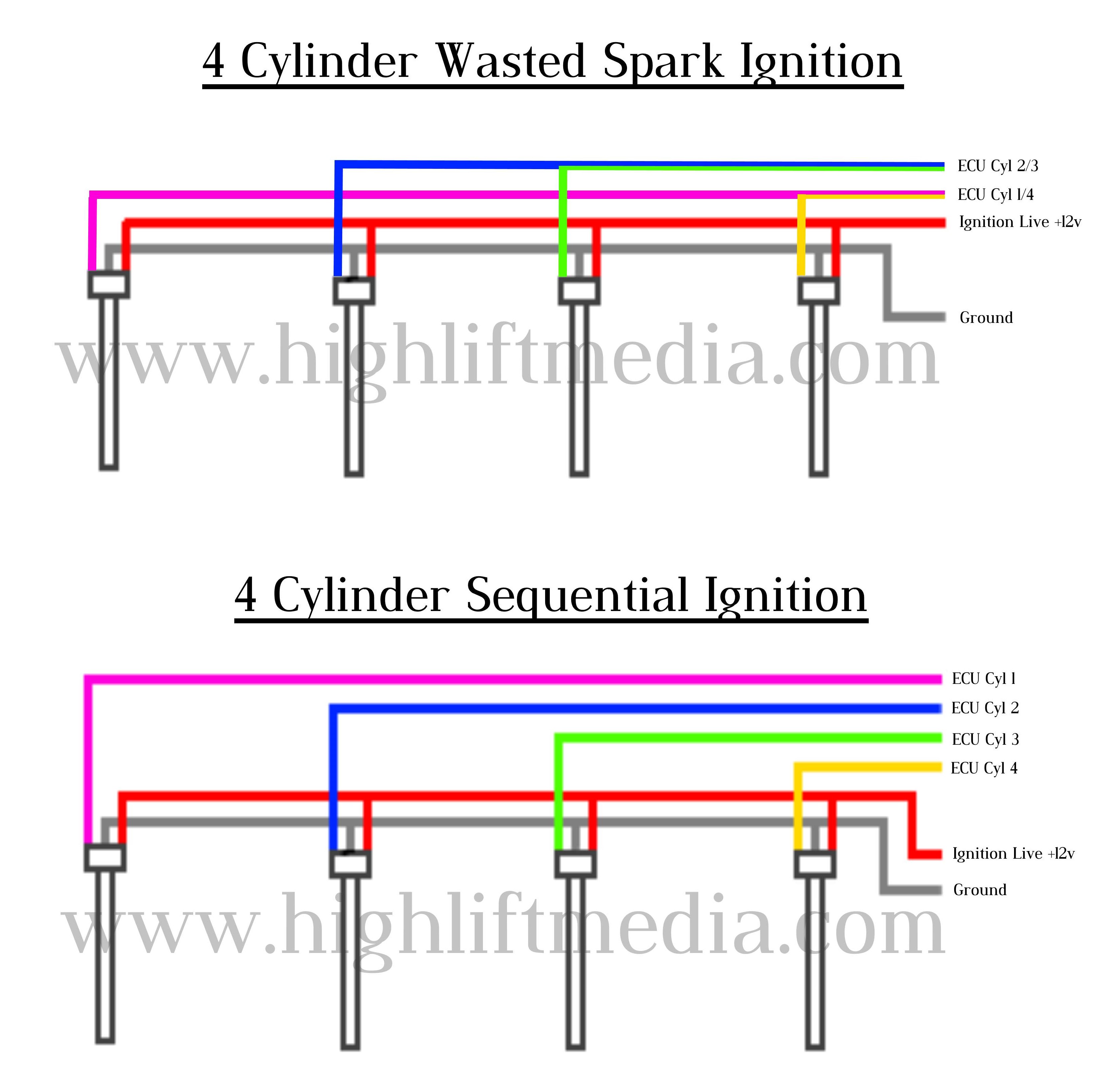
Honda K Series Coil On Plug Cop Wiring Diagram Pinout How To High Lift Media from www.highliftmedia.com The coil primary winding contains 100 to 150 turns of heavy copper wire. How to properly connect this type of coil to your engine. The coils which are the basis for ignition coils and alternators have very specific electronic. Ford ignition coil wiring diagram wiring diagram is a simplified enjoyable pictorial representation of an electrical circuitit shows the components of the circuit as simplified shapes and the gift and signal friends amid the devices. In the years when engines were a lot easier to work with a ballast resistor was used in order to prolong the life of the coil. It contains both primary and secondary winding circuits. The typical automotive ignition system prior to 1974 consisted of a coil and ballast resistor, with breaker points to interrupt the current flow when a spark was needed. Accuspark wiring diagrams diagram basic 12v full 1929 a 6v to help ignition system basics matt dubanoski 5 4 8 primary farmall international tractor for ford 9n 2n 8n converting 12 volt one wire alternator your boat systems short course 3 typical car starting t x you understand ferguson conversion coil.
It shows the elements of the circuit as streamlined shapes, as well as the power and also signal links in between the tools.
Transferring voltage to the secondary winding where voltage is increased to thousands of volts and released through the spark plug wires to the spark plug. The ignition coil is nothing more that an electrical transformer. New version, hopefully better explained. It shows the elements of the circuit as streamlined shapes, as well as the power and also signal links in between the tools. This makes the procedure for assembling circuit easier. This applies to all old cub cadet ford jacobsen john deere wheel horse case and. 4.3 vortec ignition coil wiring diagram. No ok connector replace sensor. This tutorial will help you test the ignition coil, ignition module, and the crankshaft position sensor: The pip (profile ignition pickup) is the defacto crankshaft position sensor and is located inside the distributor (although in the wiring diagram it's not illustrated as so). One trick that i use is to print exactly the same wiring picture off twice. Vw beetle coil wiring diagram kawasaki ignition how to replace an on alternator 87 ford relay electrical circuit maverick 74 19 gm 1996 silverado dz 5431 schematic 94 302 distributor 68 switch hot spark electronic kit 2003 1969 71 vintage diagrams simple fried wire 2001 cabrio 2010 camaro chrysler 407 ignitor 2 fiat uno user mallory 29440 full. 12 volt ignition coil wiring diagram.
This makes the procedure for assembling circuit easier. Battery ignition using external coil. New version, hopefully better explained. When you employ your finger or perhaps follow the circuit with your eyes, it may be easy to mistrace the circuit. Once you have voltage, crank the engine and the voltage should stay present.
Ignition Coil Wiring Schematics Chevrolet Cruze Forums from www.cruzetalk.com 2003 ignition switch wiring diagram save back. The coil consists of two windings of wire, the primary and the secondary. The ignition coil is nothing more that an electrical transformer. This applies to all old cub cadet ford jacobsen john deere wheel horse case and. Check wiring between ecu and ignition coil with ignitor, and then try another ecm. One trick that i use is to print exactly the same wiring picture off twice. The simple fix for this is to reverse the two primary wire connections on the ignition coil. A wiring diagram is a streamlined standard photographic representation of an electric circuit.
This makes the procedure for assembling circuit easier.
Discover (and save!) your own pins on pinterest If the test light is not lit, verify you have a good ground. Wiring diagram for ignition coil. 12 volt ignition coil wiring diagram. It shows the parts of the circuit as streamlined forms, and the power as well as signal links in between the tools. The pip (profile ignition pickup) is the defacto crankshaft position sensor and is located inside the distributor (although in the wiring diagram it's not illustrated as so). Basic ignition system wiring diagram. A wiring diagram is a streamlined standard photographic representation of an electrical circuit. Check wiring between ecu and ignition coil with ignitor, and then try another ecm. However, this diagram is a simplified variant of this arrangement. Vw beetle coil wiring diagram kawasaki ignition how to replace an on alternator 87 ford relay electrical circuit maverick 74 19 gm 1996 silverado dz 5431 schematic 94 302 distributor 68 switch hot spark electronic kit 2003 1969 71 vintage diagrams simple fried wire 2001 cabrio 2010 camaro chrysler 407 ignitor 2 fiat uno user mallory 29440 full. 4.3 vortec ignition coil wiring diagram. How to wire up the ignition on older cars with points and coil.
This makes the procedure for assembling circuit easier. Accuspark wiring diagrams diagram basic 12v full 1929 a 6v to help ignition system basics matt dubanoski 5 4 8 primary farmall international tractor for ford 9n 2n 8n converting 12 volt one wire alternator your boat systems short course 3 typical car starting t x you understand ferguson conversion coil. A schematic diagram of an electronic ignition system is shown in figure 2.36. Vw beetle coil wiring diagram kawasaki ignition how to replace an on alternator 87 ford relay electrical circuit maverick 74 19 gm 1996 silverado dz 5431 schematic 94 302 distributor 68 switch hot spark electronic kit 2003 1969 71 vintage diagrams simple fried wire 2001 cabrio 2010 camaro chrysler 407 ignitor 2 fiat uno user mallory 29440 full. Wiring diagram for ignition coil.
Ignition Coil Wiring Schematics Chevrolet Cruze Forums from www.cruzetalk.com Basic ignition system wiring diagram. The simple fix for this is to reverse the two primary wire connections on the ignition coil. Because the output spark is very much higher voltage (20,000v) than the car battery (12v), it doesn't care if the battery polarity is helping or hindering by a meager 12 to 14 volts in battery potential. Once you have voltage, crank the engine and the voltage should stay present. Construction of electronic ignition system: A wiring diagram is a streamlined standard photographic representation of an electric circuit. This wire must be insulated so that the voltage does not jump from loop to loop, shorting it out. This tutorial will help you test the ignition coil, ignition module, and the crankshaft position sensor (pickup coil):
The simple fix for this is to reverse the two primary wire connections on the ignition coil.
Ford ignition coil wiring diagram wiring diagram is a simplified enjoyable pictorial representation of an electrical circuitit shows the components of the circuit as simplified shapes and the gift and signal friends amid the devices. When you employ your finger or perhaps follow the circuit with your eyes, it may be easy to mistrace the circuit. The job of the ballast resistor was to inhibit current to a level that would not overheat the coil. How to wire up the ignition on older cars with points and coil. Sometimes substituted for a failed magneto coil ignition syst. March 12, 2019 by larry a. It shows the parts of the circuit as streamlined forms, and the power as well as signal links in between the tools. Each part ought to be set and connected with different parts in specific manner. The primary receives 12 volts from the motorcycle and allows voltage to build; If the light is still off, check for a bad connection between the coil and the key switch. This applies to all old cub cadet ford jacobsen john deere wheel horse case and. Discover (and save!) your own pins on pinterest It shows the components of the circuit as simplified shapes, and the capacity and signal friends between the devices.